I’ve been experimenting with home automation systems for many years. I’ve started with a few scripts controlling my aquarium lights, and evolved to a full blown home-assistant systems with many peripherals, many of whom are home made.
the current configuration works for the last 4 year with little modifications. It does what I need, and I rarely even upgrade the software (unless the SD card goes bad).
but a few days ago I noticed my FreeNAS has a home-assistant plugin to easily install inside a jail. so I gave it a try, and it looked nice. the problem was the old system was installed on a raspberry pi located under the aquarium cabinet, and all the relays to control the aquarium are connected physically to the GPIO’s of the pi. the FreeNAS server sits under my TV, so I needed a way to remote control those relays. and so begins the 3rd generation of my system.
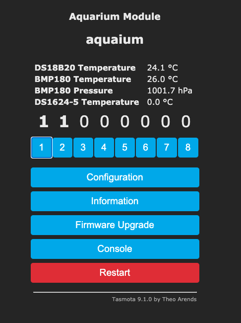
I had a few SONOFF devices laying around, so I’ve took one and programed it with TASMOTA. instantly HA recognised it automatically. I hooked it up to a lamp, and controlled it from my computer. hurray!
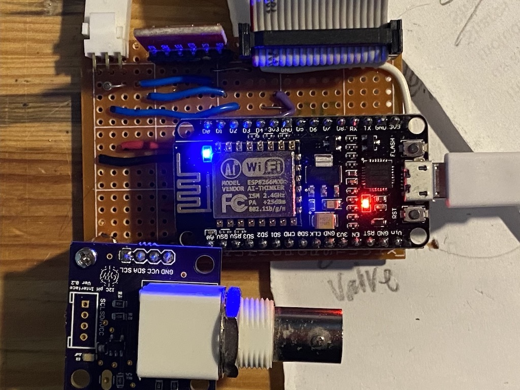
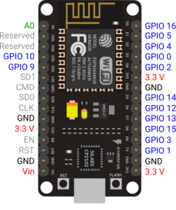
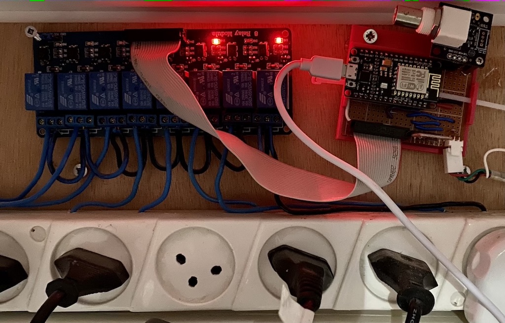
to control all the power sockets, I needed something with more IO’s. so I grabbed a NODEMCU I had from my experiments with the ESP-8266. again flushed it with TASMOTA and started playing around. i’ve got 8 relays, so that’s 8 GPIOs. but I wanted to add as many of the original capabilities which include ds18b20 to measure water temperature, a PH probe, BMP180 for barometric pressure, 433MHz transmitter and receiver.
I’ve quickly sketched a pcb based on my raspberry pi version. but before sending it to china for manufacturing, i decided to try and build a breadboard version and check everything work. and lucky i was to do so, as there we a few things that didn’t.
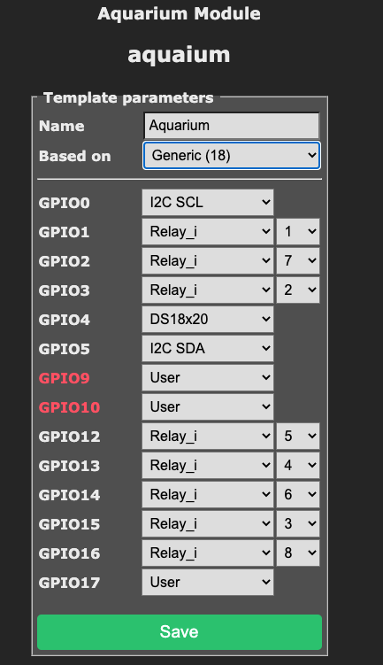
- GPIO 9 & GPIO 10 can not be used by TASMOTA. you might be hinted by the red font they appear on the configuration screen. but why are they there to begin with ? i don’t know. every time I used them the configuration failed.
- since I could not use pin’s 9 & 10, I had to leave out the 433MHz unit which was used to control legacy power sockets I have. I might use another ESP-8266 as a RF gateway, or upgrade the sockets to WiFi units.
- GPIO 16 can not be used for i2c. not sure why either. It seems only GPIO 0 to 15 have internal pull-up resistors. I’ve added an external 10K but it didn’t help. so I re-routed the i2c pins to lower GPIOs
- pins 14, 15 were making the device hang on power-up. pin 15 is documented to need to be not pulled up. i tried a pull-down resistor but did not help. i eventually disconnected them both from the relays.
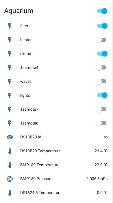
I’ve connected everything, and after some tweaking all functions worked correctly. so I’ve copied the old automation rules to the new system.
a nice weekend project