some time ago i got a nice deal on a buddipole antenna. I already had an alexloop which i was very happy with, but I could not resist the temptation of a “real” dipole that could take the full 100W from my rig. so i went online and ordered one.
after i got the package i went on and setup the rig and antenna, and it worked ok. but i wasn’t happy and wished for more… it took a lot of time to assemble and result were on par of the alexloop.
At the last hamvention i had a chance to talk to the buddipole engineers at their booth. the first question they had was “did you checked it with an antenna analyzer” ? “no”, i’ve replied. “so you should” they said. and it sounded like a solid advice. now i had a plan…
so I’ve headed to the MFJ booth next door and asked for one, and how crashed my spirit was when I noticed the price tag. it was $200-$400 for a very basic model. i guess it’s not a lot to pay for such an instrument, but my budget was already exhausted.
I tried to look online for a cheap analyzer, but it looked like real garbage. but then i’ve noticed some links to DIY analyzers. I could not resist the temptation.
i started by looking at the design by Beric Dunn K6BEZ. while not exactly a SWR meter, but an impedance meter, it was good enough for my need.
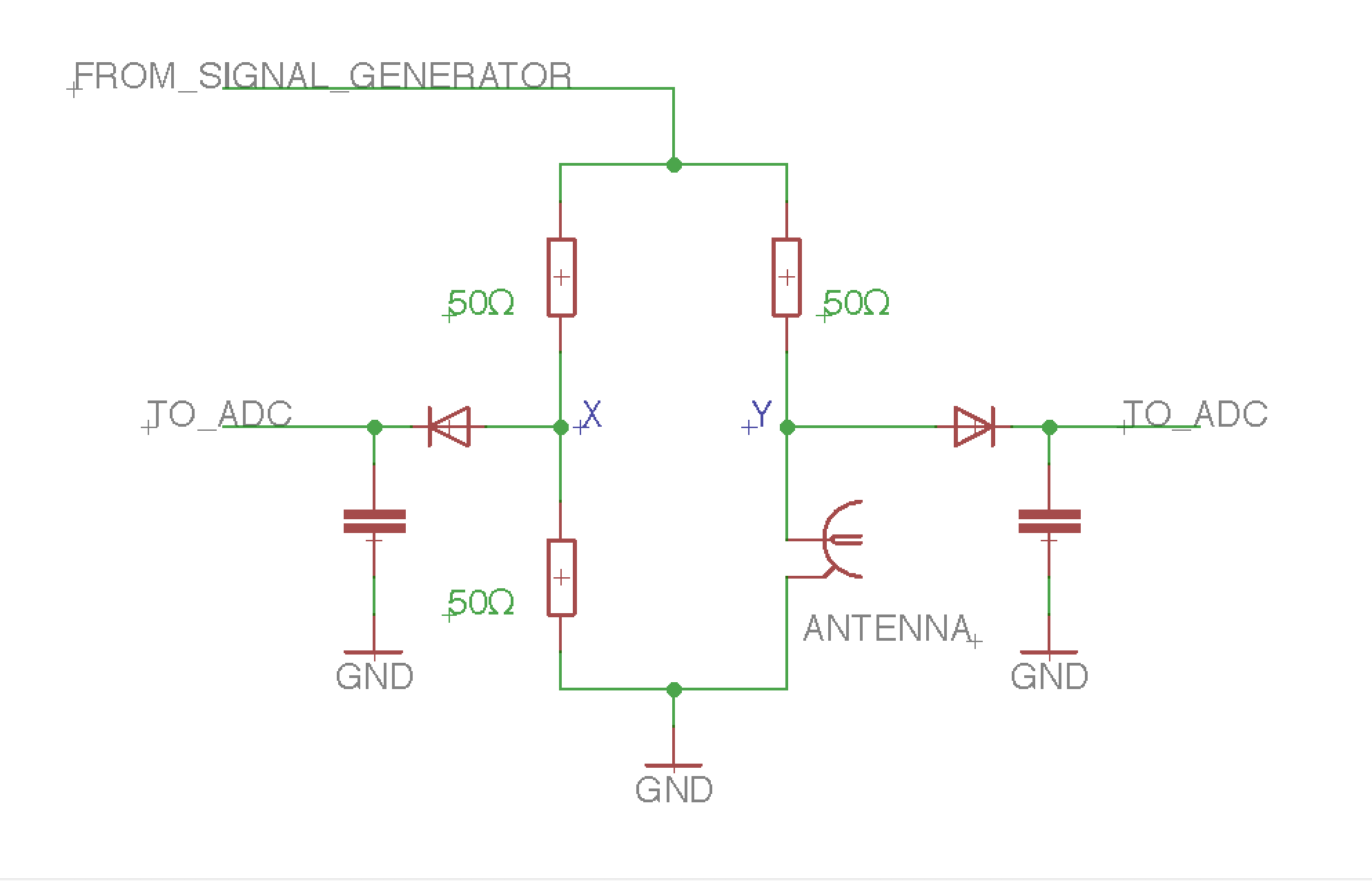
the basic design is simple enough and modifiable, it contains a AD9850 signal generator (about $8 on eBay), which drives an H-Bridge. Vx is always half the input voltage. if the antenna is 50 Ohm, the voltage between points X and Y should be zero. if the impedance is low, Vy will drop to zero, and so on. so both points are driven to an envelope detector comprised of a germanium diode and a capacitor, which is then sampled by an arduino and results are shown on the display.
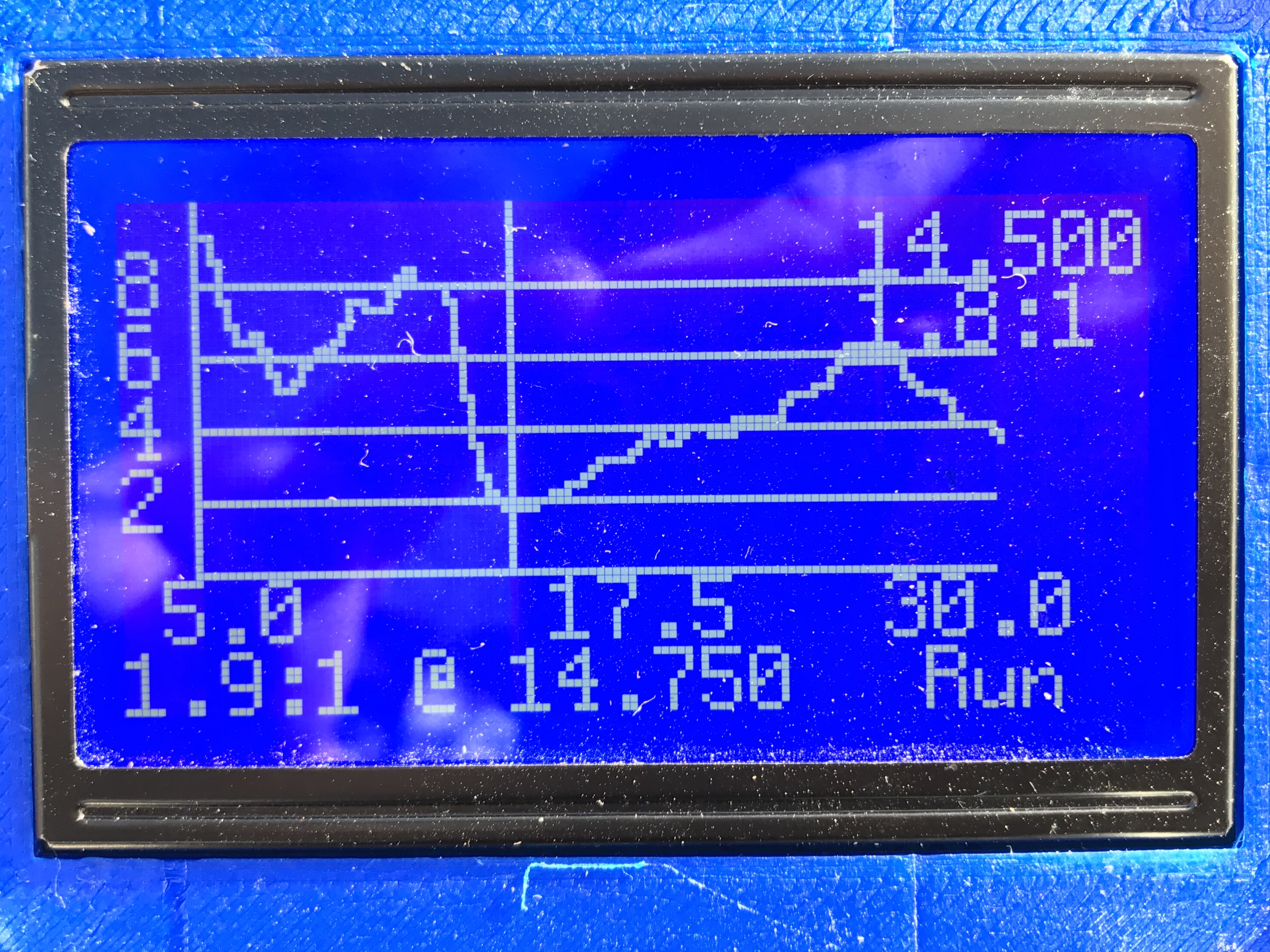
there were a couple of things i want to change to make it more portable and appliance like. first I wanted a graphic screen, so i can display a frequency graph without connecting it to a PC. and I also wanted to use a rechargeable battery for ease of use.
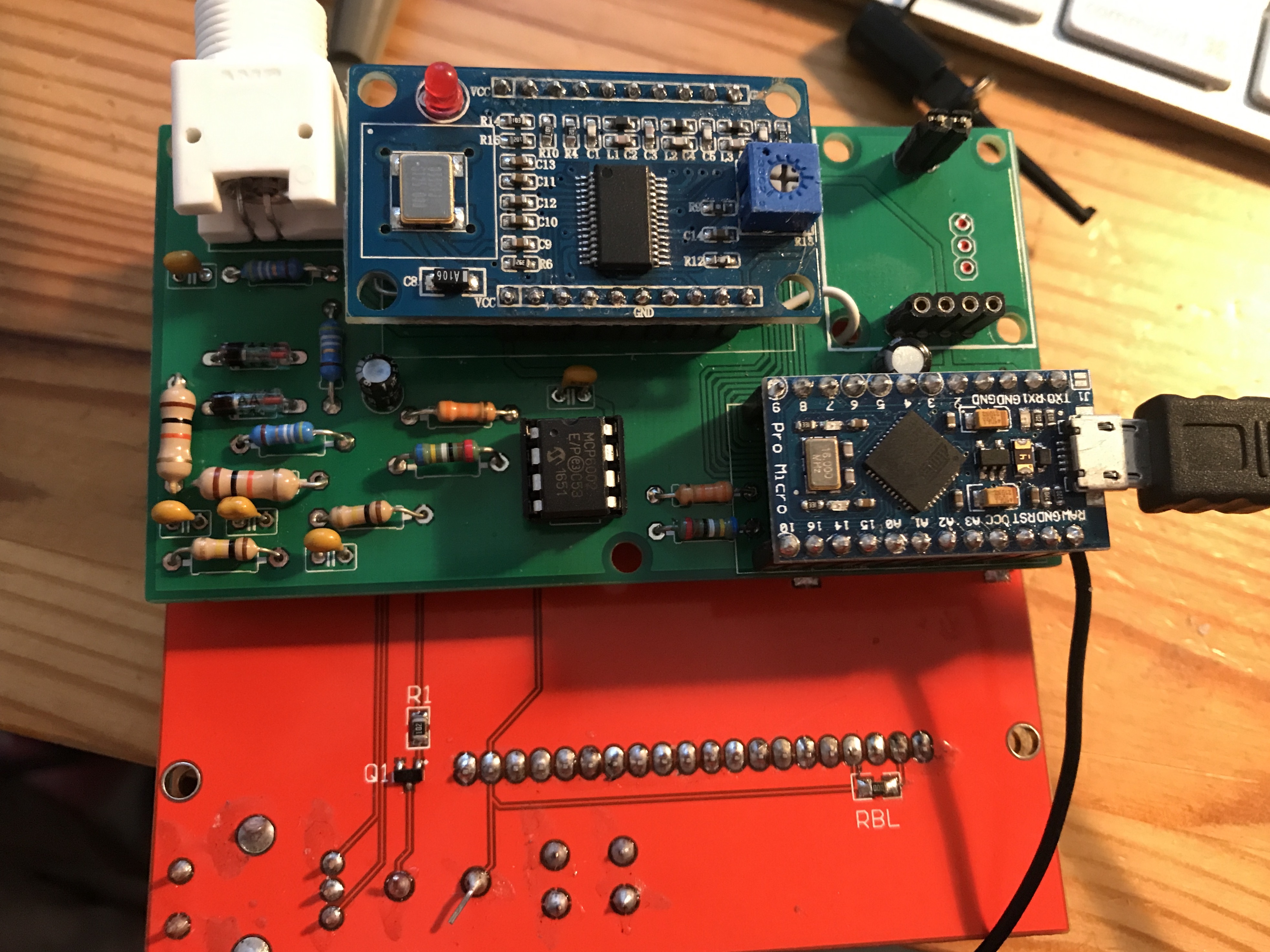
I found a display module that is used in prusa 3D printers for $10. it got a 128*64 display, a rotary encoder and a push button. I had a LiPo charger/Regulator which I once bought (and regrettably is no longer available). so I designed a PCB to host all the components, modified the software to add a graphic UI and 3D printer an enclosure.
the result look as good as any professional analyzer I saw.
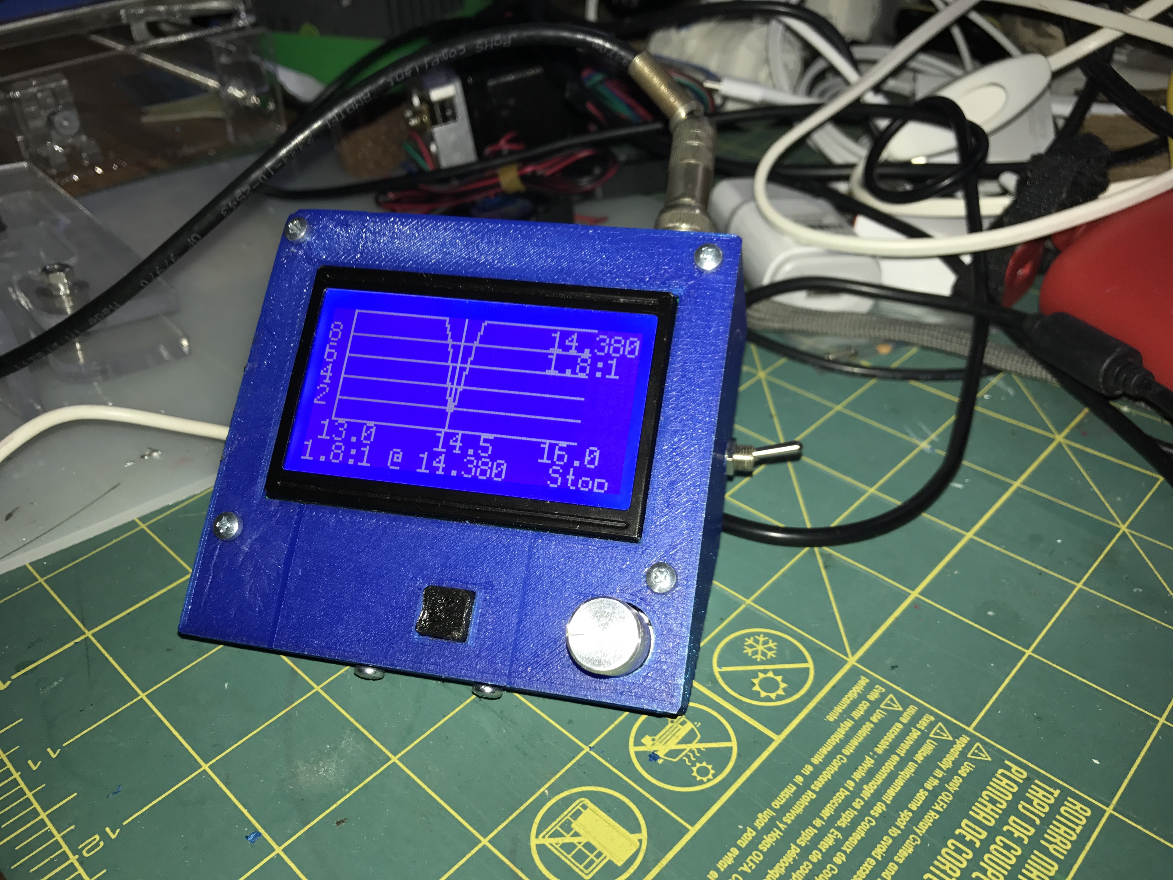
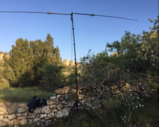
to test the device I connected it to the alexloop. mag loops are notorious for their narrow Q, but here it was an advantage as I could see the freq response very clearly. since I had no reference analyzer, I simply tuned my antenna to lowest SWR at the transceiver, and then measured the same configuration with my analyzer. results were surprisingly good.
| Freq on RXTX | SWR | Freq on Analyzer | SWR |
|---|---|---|---|
| 7.040 | 2.2 | 7.060 | 3.4 |
| 14.074 | 2.2 | 14.080 | 2.0 |
| 21.200 | 1.1 | 21.230 | 1.6 |
I then finally tried the buddipole. i was still very labor intensive to set up. and performance wise i did not get the desired “WOW” feelings. I guess I still need to improve my antenna tuning skills….
source files can be found here
One thought on “DIY HF Antenna Analyzer”
Comments are closed.