This is my solenoid motor. I started this project 3 years ago, and every now and then made some progress, and then forgot about it for another year.
The basic model uses the crankshaft as the timing mechanism. One wire is connected permanently to the shaft.
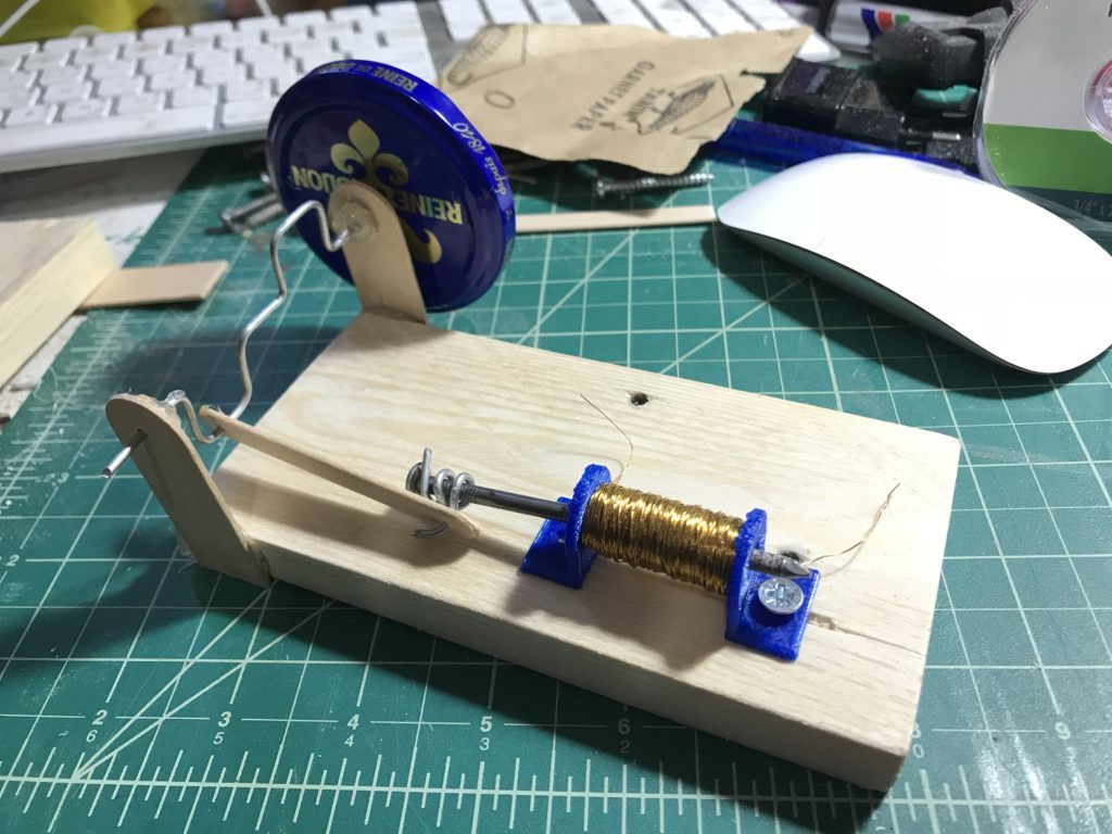
The shaft has a cam that touches a probe only when the shaft is in the right position. Then the circuit is closed and the electromagnet is energized
It is a simple and elegant solution, but there are 3 drawbacks to this mechanism.
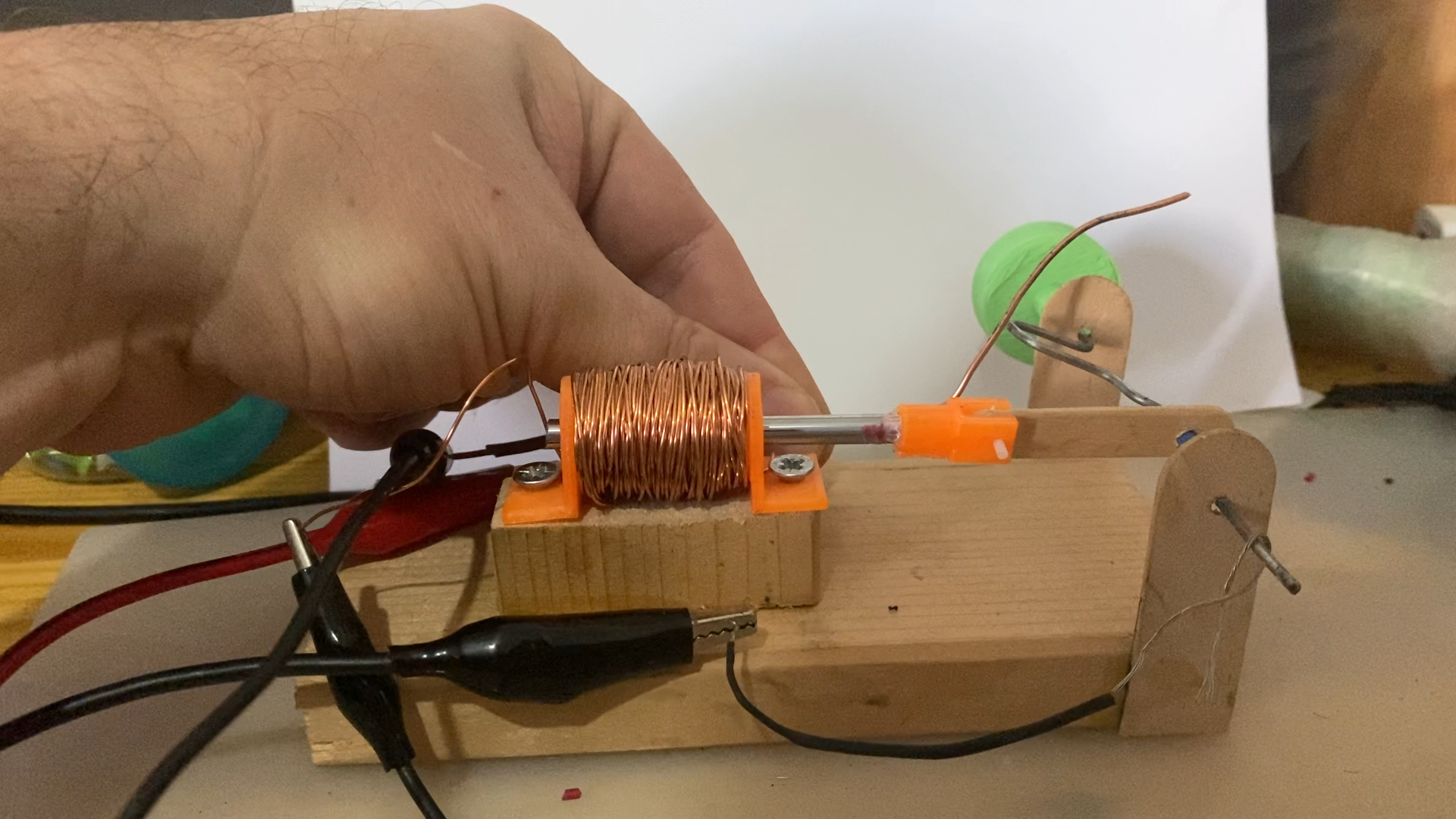
- The first are the Arcs that appear when the wires touch each other, I think it’s cool, but it degrades the contact quality
- since my mechanical skills and tool are minimal the secord downside is that there is a lot of friction between the leads
- And lastly, It’s hard to time the system quite right
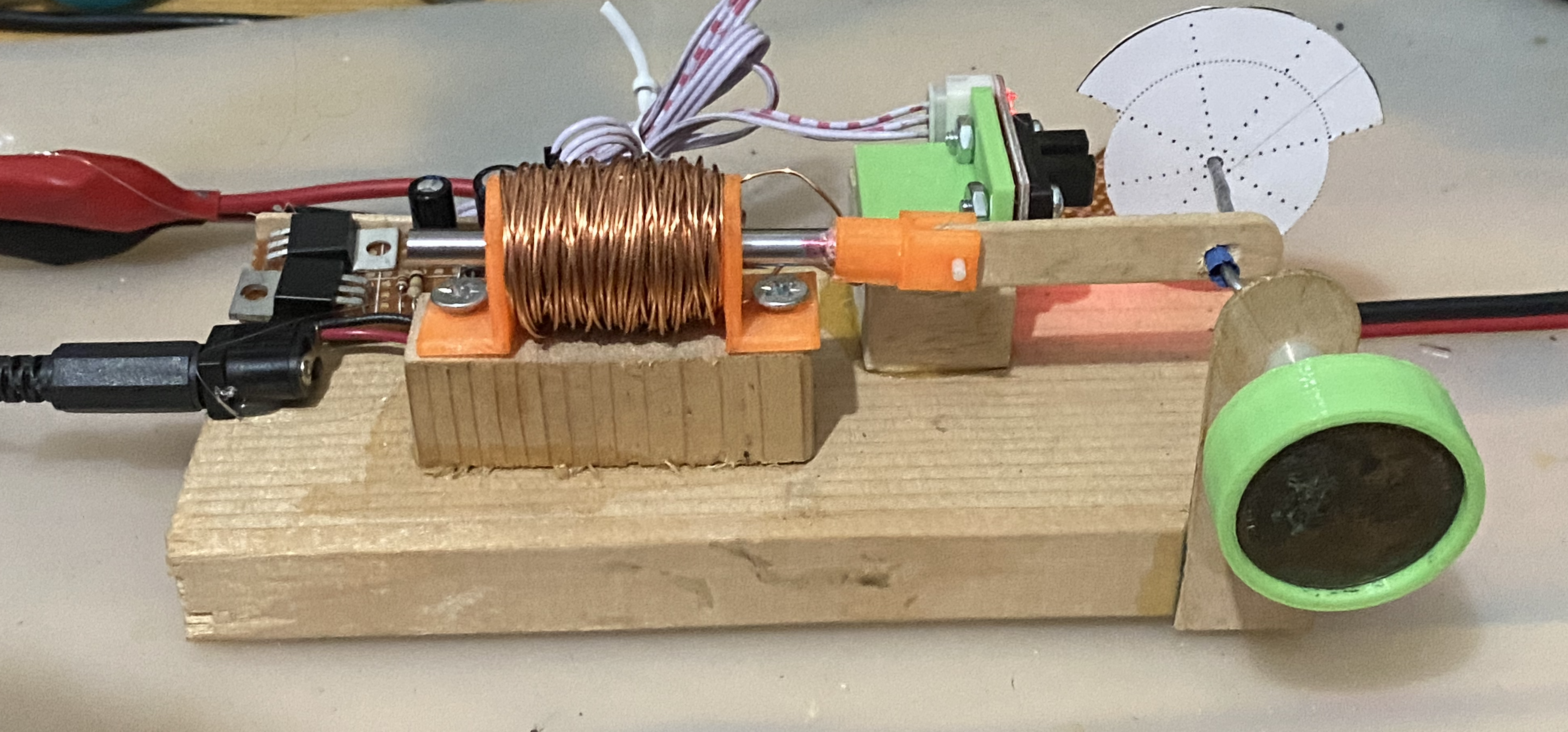
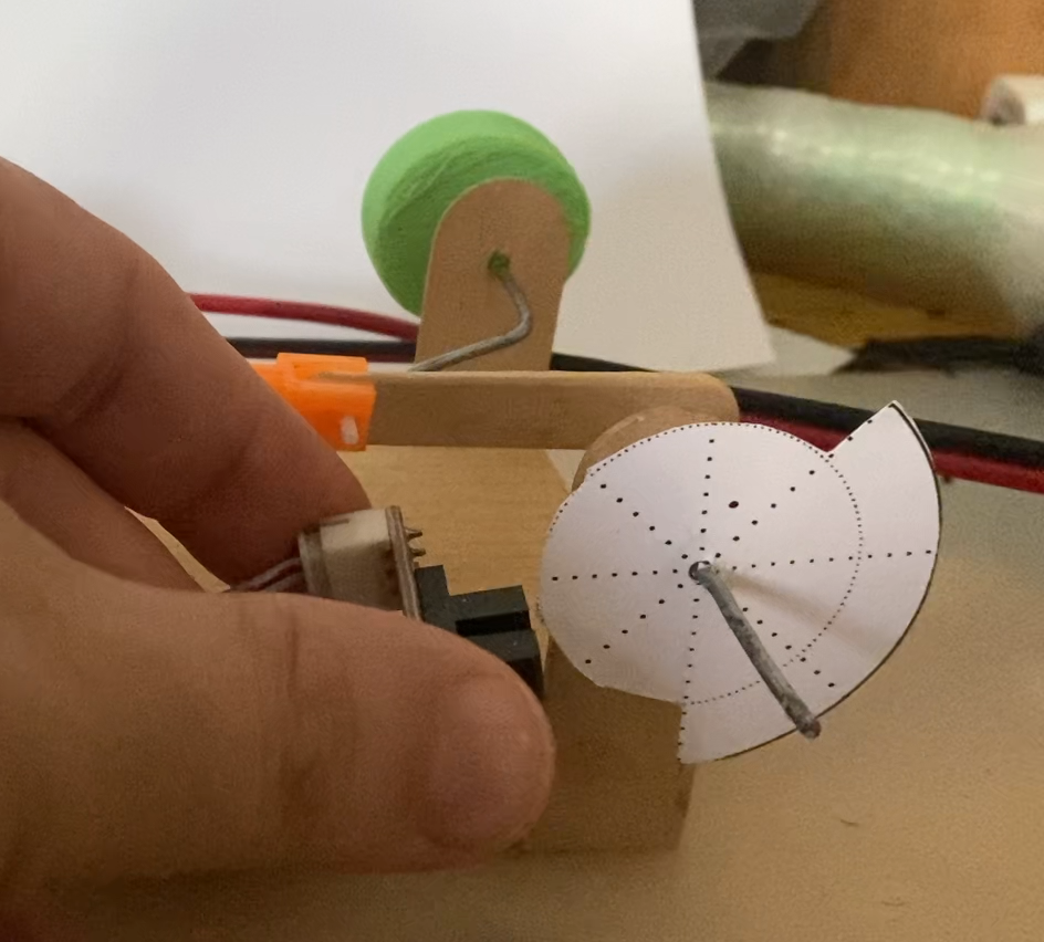
Recently I saw a youtube video that made me take another route: I used a simple optical edge sensor, then I cut a circle out of cardboard to act as the timing disk
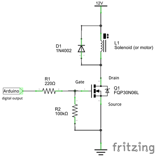
I also built a small circuit that uses a MOSFET to act as a switch
When the disc radius is small, the sensor is off and no power is delivered to the electromagnet
When the radius is big enough the sensor activate the switch and powers the electromagnet to make a engine bang
I’ve tested the setup and to my surprise it worked the first time
So I tweaked it a bit and glued everything together.
Now it runs like a dream.
edit: the cardboard disk can actually act as a flywheel, to the big metal weight is not needed.
measuring the sensor signal, I get 10-15 Hz which is around 900 RPM, at 1000 RPM thing do start to fall off