Battery-powered IoT products can look deceptively simple. Choose a wireless microcontroller, connect a battery, add a USB-C port if you want the device to be rechargeable, and the job appears to be done. Easy.
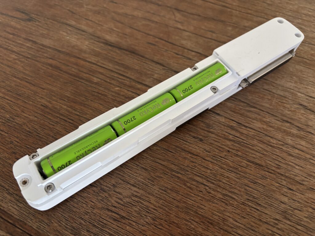
In practice, reliable battery-powered wireless design is a system-level exercise. The processor, radio, sensors, voltage regulator, user interface, communication protocol, firmware behavior, battery chemistry, and even the enclosure can all affect operating life.
Whether the product uses the large battery in a vehicle or the tiny rechargeable batteries in a pair of earbuds, conserving energy is almost always important. In this article, I will explain the fundamental principles that guide the design of an efficient battery-powered wireless device.
Choosing the wireless processor
The main processor and radio are natural starting points, but there is no universally best choice. The right device depends on the wireless standard, processing requirements, software ecosystem, price, size, and power budget.
An ESP32-family device can be an excellent choice when Wi-Fi is required. It provides substantial processing capability, a mature development ecosystem, and highly integrated wireless functions at a competitive cost. The tradeoff is that Wi-Fi communication—and especially maintaining a connection—can consume significant energy. An ESP32 can still work well in a battery product when communication is infrequent and the processor can spend most of its life in deep sleep.
A Nordic nRF52- or nRF53-family device is often attractive for Bluetooth Low Energy and other low-power wireless applications. These devices are designed around low-energy operation and can support very low sleep current, efficient wake-up behavior, and flexible peripheral control. They are frequently a strong fit for sensors, beacons, wearable products, and devices that communicate with a nearby gateway or phone.
The comparison is not simply “ESP32 uses more power; nRF uses less.” The application decides the result. If the product needs direct Wi-Fi access, adding an external Wi-Fi radio to a low-power processor may create more complexity, cost, and energy use than selecting an integrated Wi-Fi device. Conversely, using Wi-Fi where Bluetooth Low Energy would fully satisfy the requirement can impose an unnecessary energy penalty.
Other options, such as sub-GHz radios, Thread, Zigbee, LoRa, LTE-M, or NB-IoT, may be more suitable depending on range, infrastructure, latency, bandwidth, and deployment environment. Select the communication architecture before selecting a favorite chip.

Sleep time, awake time, and the cost of communication
Most battery-powered devices do not need to operate at full power continuously. Instead, they alternate between brief periods of activity and much longer periods of sleep. During sleep, the processor stops executing normal code and disables as many internal circuits as possible. It waits for a specific event, such as a timer expiring, a button being pressed, or a sensor detecting a change, to wake it. so only the specific part of the circuitry is left powered up.
This repeating pattern is called a sleep/wake cycle. The objective is to keep each active period as short as possible and spend the greatest practical percentage of time asleep. The exact balance depends on the product: a temperature sensor may sleep for several minutes between readings, while a safety device that must respond immediately may need to wake frequently or keep part of its receiver active.
A typical low-power device follows a sequence such as:
- Sleep while waiting for a timer, button, sensor interrupt, or incoming event.
- Wake and initialize the hardware that is needed.
- Take a measurement or perform a calculation.
- Establish communication and transmit or receive data.
- Confirm success, store any required state, and return to sleep.
Reducing awake time is often as important as reducing active current. Firmware should avoid unnecessary delays, repeated initialization, excessive measurements, verbose radio exchanges, and long network timeouts.
Failed communication must also be included in the design. A device with weak coverage may repeatedly reconnect or retransmit, using far more energy than it did on a development bench. A sensible retry policy, local data buffering, adaptive transmission intervals, and a defined failure mode can protect battery life.
Latency creates a direct tradeoff. A product that must respond immediately may need to keep a receiver active or wake frequently to check for messages. A product that can tolerate a delayed response can sleep for longer. Battery life is therefore not only an electrical specification; it is also a product requirement that must be balanced against the user experience.
The product’s operating profile
A component that consumes almost no power most of the time can still create a problem if it draws a large current for a few milliseconds, or if it is never fully turned off.
The goal is therefore not simply to select “low-power” parts. It is to understand where energy is used, minimize that energy without compromising the product’s function, and build a realistic model of how the device will behave in the field.
Before selecting components, define what the device must actually do:
- How often does it measure, transmit, or receive data?
- How quickly must it respond to an event?
- Must it remain continuously connected to a network?
- What wireless range and data rate are required?
- How often can the battery reasonably be charged or replaced?
- Will the device operate in heat, cold, or other difficult conditions?
- How long must it remain usable if communications repeatedly fail?
These questions determine the device’s duty cycle: the proportion of time spent asleep, awake and processing, transmitting, or receiving. For many products, the duty cycle matters more than a small difference between two components’ headline sleep-current specifications.
A sensor that wakes for 100 milliseconds once every minute has a very different energy profile from a device that maintains a live Wi-Fi connection or must respond instantly at any time.
When comparing devices, consider:
- Current in each relevant sleep and active mode
- Radio transmit power and receiver current
- Time required to start, connect, and complete a transaction
- Wake-up sources and wake-up time
- Memory retention during sleep
- Ability to disable internal peripherals
- Processing performance per unit of energy
- Radio sensitivity and retransmission behavior
- Module certifications, antenna design, software support, cost, and availability
A higher active current is not automatically worse. A faster processor may finish a task sooner and return to sleep, consuming less total energy than a slower processor running for longer.

Deep sleep only helps if the whole system sleeps
Modern microcontrollers offer several low-power states. In light sleep, more internal state and peripherals may remain available, allowing a quick wake-up. In deep sleep, most of the device is turned off, reducing current substantially but usually increasing wake-up time and requiring some software reinitialization.
The appropriate mode depends on the required response time and how long the device will remain inactive. Entering the deepest possible sleep for a few milliseconds may save less energy than it costs to shut down and restart.
It is also important to distinguish between the processor’s sleep current and the complete circuit’s sleep current. A microcontroller may consume only a few microamps while sleeping, but a sensor, indicator LED, USB interface, level shifter, pull-up resistor, or poorly chosen regulator can consume many times that amount.
Peripherals should be managed deliberately. Depending on the component, firmware may place it into standby, disable its clock, isolate its signals, or remove its power completely using a load switch or transistor. Input/output pins must also be configured carefully. A floating input or a signal driven into an unpowered peripheral can cause unexpected current and, in some cases, unreliable operation.
The power supply deserves equal attention. A regulator that is efficient at 100 mA may perform poorly at the few microamps typical during sleep. Its quiescent current, the current the regulator consumes merely to remain operational, may dominate the sleep budget. The selection of a buck converter, boost converter, low-dropout regulator, or direct battery connection should be based on the battery voltage range and the device’s entire load profile, not just its maximum current.
Selecting the battery
Battery selection involves much more than capacity. Relevant factors include:
- Nominal voltage and discharge curve
- Maximum continuous and pulse current
- Energy density, size, and weight
- Self-discharge and shelf life
- Rechargeable versus replaceable operation
- Charging time and expected cycle life
- Temperature performance
- Safety, protection, shipping, and certification requirements
- Cost, availability, and replacement logistics
Primary lithium cells can provide high energy density and long shelf life for devices expected to operate for years without charging. Alkaline cells are widely available and economical, but their voltage and usable capacity depend strongly on load. Coin cells are compact and can work well with very low average current, yet many cannot support large radio peaks without careful design. Rechargeable lithium-ion or lithium-polymer batteries can deliver substantial current and are suitable when charging is practical, but they require protection, charge management, and consideration of aging and storage conditions.
No chemistry is best for every device. The battery, power electronics, enclosure, charging method, maintenance plan, and expected use must be designed together.
Predicting battery life
After making the initial component and battery selections, we want to know what battery life the design can actually achieve. We could (and often do) build a prototype and measure it, but first we can develop a useful estimate.
The basic calculation uses the average current over one operating cycle:
Average current = sum of (current in each state × time in that state) ÷ total cycle time
For example, consider a device that:
- Draws 12 mA for 0.2 seconds while measuring
- Draws 80 mA for 0.1 seconds while transmitting
- Draws 10 µA for the remaining 59.7 seconds
Its approximate average current is:
[(12 mA × 0.2 s) + (80 mA × 0.1 s) + (0.010 mA × 59.7 s)] ÷ 60 s ≈ 0.183 mA
With an ideal 2,000 mAh battery, the simple estimate would be:
Battery life = 2,000 mAh ÷ 0.183 mA ≈ 10,930 hours, or about 15 months, we’ll usually multiply that by a safety factor of 80%-90%.
That is a useful starting point, not a product guarantee. A realistic prediction applies allowances for:
- Regulator and conversion losses
- Battery capacity variation and aging
- Battery self-discharge
- Reduced usable capacity at low or high temperature
- Peak-current limitations and voltage drop
- Wireless retries and variations in signal strength
- Startup current and infrequent maintenance functions
- Leakage through components and the circuit board
- Changes in behavior as battery voltage falls
- A safety margin for real-world use
The battery’s rated capacity is normally measured under defined conditions that may not resemble the product’s load. Short radio-current peaks can cause the battery voltage to dip below the device’s operating threshold even while energy remains in the cell. A capacitor may help supply short peaks, but it does not correct every battery or power-path problem.
Spreadsheets and simulations are valuable early in development, but measurements are essential. Current should be captured across complete operating cycles with equipment capable of resolving both microamp sleep current and fast radio peaks. Long-duration testing then reveals unusual events that a short test may miss.
Why a large USB power bank is often not the answer
In one of my projects, we were struggling to achieve the specified battery life. After a progress presentation, the CEO said, “I just bought this huge power bank to charge my phone. It has much more capacity than your calculations require. why not use that?”
It was a reasonable question. A large USB power bank may appear to solve the problem by offering thousands of milliamp-hours at low cost. For prototypes, it can be convenient. For a finished low-power product, however, it frequently performs poorly.
First, the stated capacity usually refers to the internal cell at its native voltage, while the USB output is converted to 5 V. Conversion losses mean that the usable energy at the output is lower than a direct comparison of milliamp-hour ratings suggests.
Second, many power banks are designed to charge phones, not to supply a device drawing only a few microamps or milliamps. Internally, a typical power bank contains a battery-management and power-conversion circuit. This circuit protects the cell, controls charging, boosts the cell voltage to the 5 V USB output, and monitors whether a load is connected.
Because the converter itself consumes energy, many power banks automatically turn off their output when the current falls below a minimum threshold. When our IoT device enters deep sleep, its current may drop so low that the power bank interprets this as “nothing is connected” and shuts down. The device then cannot wake itself because its power has been removed completely.
Finally, even when the output remains active, the power bank’s control electronics and voltage converter consume energy while the application is asleep. The device may then convert the 5 V output down again to its own operating voltage, adding another conversion stage and more losses. The result can be disappointing runtime despite the physically large battery.
Battery capacity cannot compensate indefinitely for an inefficient architecture. Improving a device from 5 mA average current to 50 µA creates a hundredfold improvement; fitting a battery a hundred times larger is rarely practical.
Design for energy, then verify the real product
Successful battery-powered wireless devices are created by managing energy across the entire system. Start with the required behavior, choose the communication technology and components accordingly, control every peripheral, minimize unnecessary awake time, and evaluate the power supply at both sleep and peak loads.
Build an energy budget early and update it as the design evolves. Then verify it on real hardware under realistic temperatures, signal conditions, battery states, and usage patterns. The most important battery-life problems are often found not in a datasheet headline, but in the interactions between hardware, firmware, wireless behavior, and the real world.
At TAYIO Technologies, we treat power consumption as a system requirement from the beginning of product architecture through prototyping and validation. That approach reduces technical risk and helps turn an attractive battery-life estimate into a product that can meet its operating goals in the field.
Leave a Reply