Insulin pumps are nothing new. they have been around for decades, easing the administration of insulin to diabetes patients. most pumps look like an old ipod device, with a flexible tube going into the infusion set that punch through the skin and delivers to needed medicine to a fat tissue in the body. the omnipod dash combines all those element into one package the roughly side of a matchbox. the small size does limit the amount of insulin carried on board, but it well suited to children and adults that react to smaller doses.
the design restrictions of medical equipment are ample. and making such accurate device that is cheap enough so it can be discarded after only 3 days of work is an amazing feat. so I could not resist the temptation of opening up a used device and find out what’s inside.
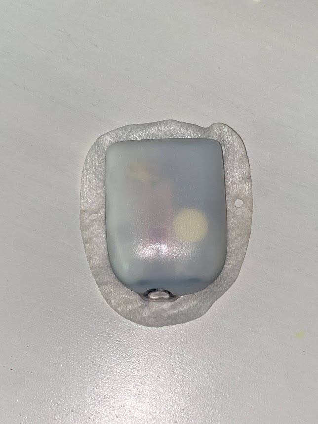
on the top side, there is nothing much to see. just the plastic cover
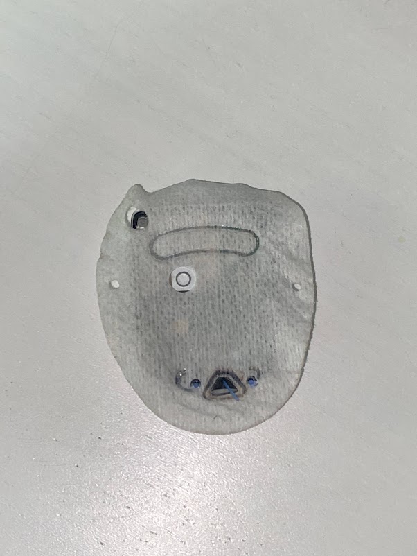
the bottom side is mostly covered with the adhesive plaster that holds the unit firmly to your body. on the top left side there is the filling port, where you insert the insulin before use (insulin is a sensitive material that need special care, so the unit comes empty). on the bottom side there is the “cannula” which is the blue tube that is inserted into the skin. it can be seen here, as it’s a used unit. we’ll see how it punches through later on.
so first thing, I’ve removed the tape, and found that the top plastic cover is welded into a transparent plastic plate, underneath it lays the electronic PCB, and the insulin reservoir (on the to left). taking these two pieces apart was not an easy thing to do, but this pod is water tight so I guess that was the result.
after I managed to separate the covers, I finally got to see the inner assembly.
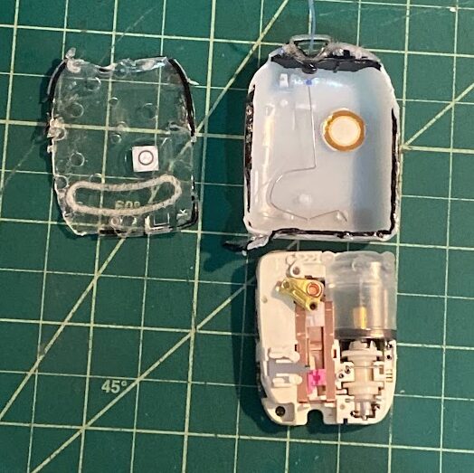
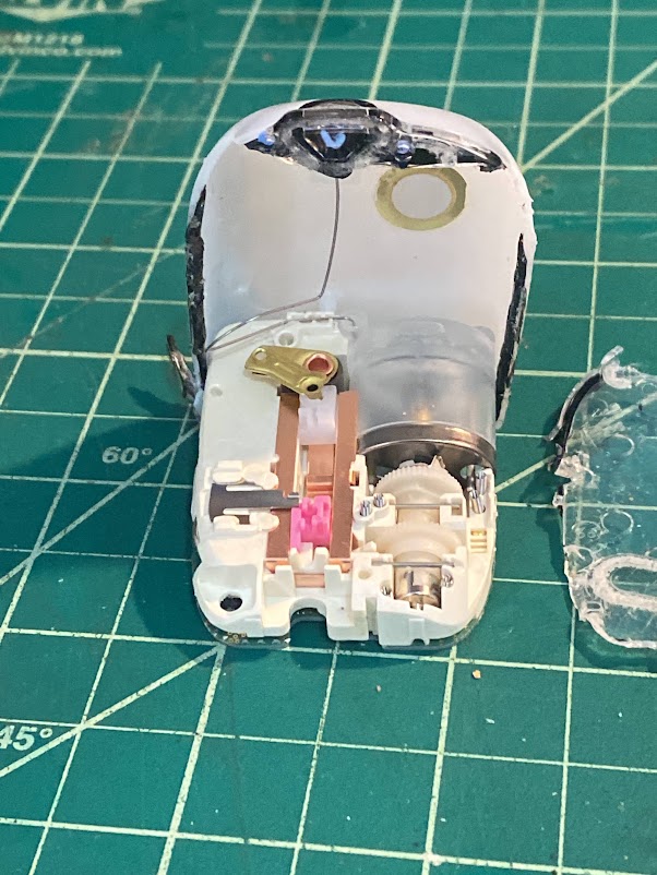
on the bottom of the assembly there’s the PCB we saw earlier. the top right side is the reservoir, and we can now see the plunger on a screw connected to a small motor on the bottom right side. amazingly, there is only one motor that control both the administration of insulin, the activation of the unit once insulin is inserted into the reservoir, and the release and retrieve of the spring loaded needle (can be seen connected to the white cover) and tube (connected to re reservoir). on the top cover there is also a piezo that acts as a buzzer.
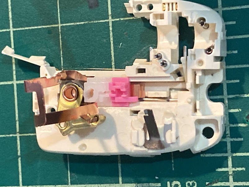
I haven’t quite figured out how the needle insertion works, but the main components are a pink slide the move on rails under the bronze cover, and being held in place by a latch on the left side. there is also a white slide connected to an arm with a very strong spring, I assume it is what retracts the needle after the plastic tube is inserted to the skin. and again, everything is activated and coordinated by the same motor that drives the reservoir. this must have been quite a cost saving to justify the mechanical complicity.
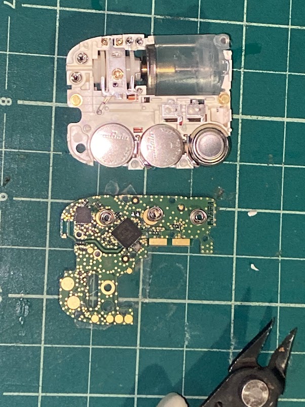
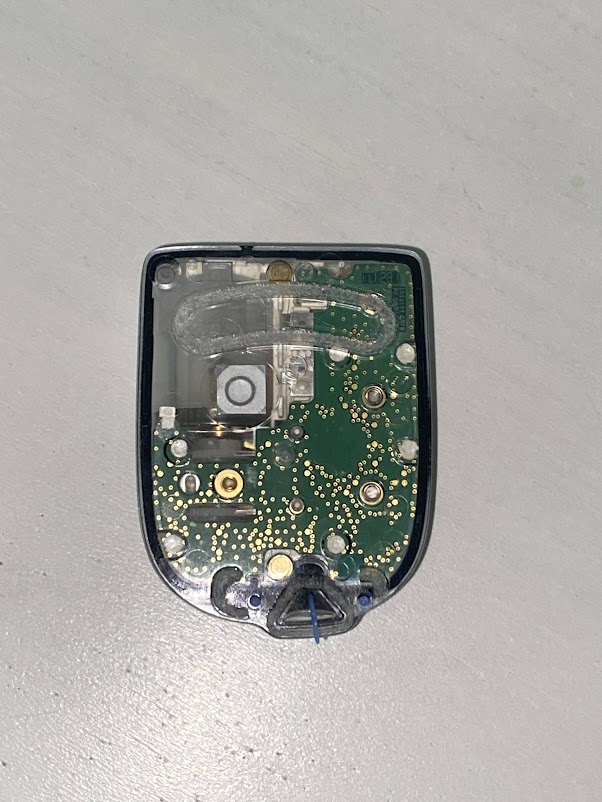
lastly, there is the other side of the PCB, which contains the brains of the device which is a NXP EX2105F 32 bit arm7 processor, and QN3000 which I could not find a datasheet, but my guess is it might be a bluetooth chip, as this is how the unit is controlled and there is no mention of wireless capabilities on the processor. there are also spring connectors to 3 LR44 batteries, and pads to connect with pins on the mechanical assembly.
Leave a Reply